Using the Trace Polyline Tool in a CAD Environment
The ‘Trace Polyline’ tool is vital in a CAD environment for creating a single, continuous polyline from existing segments. This tool is especially useful when accuracy and connectivity are essential in complex designs. By tracing and merging polyline segments, users can achieve a streamlined and cohesive design.
Why It’s Needed
In CAD, maintaining precise connections between lines is crucial for ensuring that designs are accurate and easy to modify. The ‘Trace Polyline’ tool simplifies this by allowing users to trace existing segments and create a unified polyline that follows the exact path of the original segments. This process is essential for maintaining design integrity, especially in projects requiring detailed and interconnected elements.
Steps to Use the Trace Polyline Tool
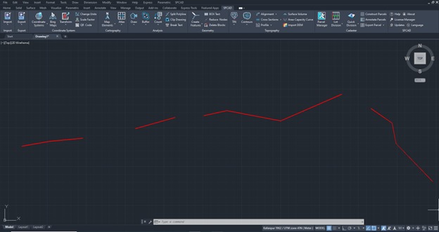
- Access the Tool
Navigate to the Geometry panel and go to the dropdown of ‘Create Features’ and select ‘Trace Polyline’ or type TRC_SP in the command prompt. - Choose a Starting Point
Select a starting point to begin tracing. The starting point can be a polyline node or any other point on the drawing. - Select the Polylines
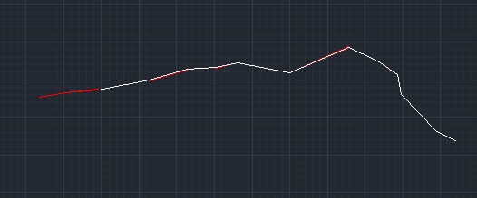
Click on the polylines one by one to trace them. Tracing starts at the chosen start node and ends at the end node of the selected polyline. To reverse the tracing order and start from the end node, enter rev. - End the Tracing
Press E to end tracing. Choose an ending point, which can be anywhere on the drawing or the end node of the last traced polyline. - Finalize the Polyline
The traced polyline is placed on top of the original segments, ensuring accuracy and alignment with the existing design.
By following these steps, you can effectively use the ‘Trace Polyline’ tool to enhance your CAD designs, ensuring they are precise and well-connected.