Overview
3D polylines in CAD are essential for civil engineering, land surveying, and infrastructure modeling. They represent terrain, alignment paths, and utility lines in accurate three-dimensional space. In SPCAD, the Add Node to 3D Polyline tool makes editing smoother by allowing users to insert new vertices with precise elevation interpolation.
Unlike 2D polylines, 3D polylines store X, Y, and Z coordinates for every vertex, which ensures that terrain and elevation data remain consistent. However, manually adding new vertices can be time-consuming and error-prone. This SPCAD feature solves that problem by automatically calculating the new point’s Z-value based on the nearest adjacent vertices.
Usage of the Tool
- Editing survey lines to add new measured points
- Adjusting terrain breaklines in surface models
- Inserting design points for infrastructure features like pipelines, road centerlines, or contours
- Ensuring geometric accuracy while preserving elevation continuity
Workflow Steps
- Activate the Tool
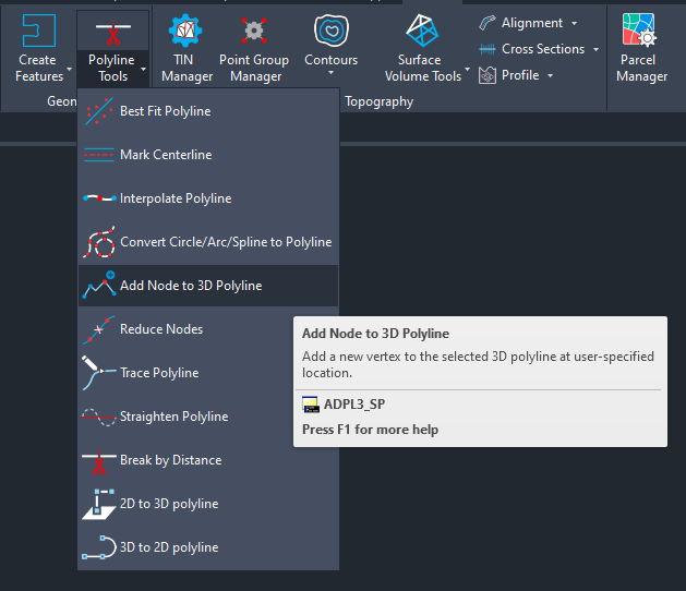
Launch the Add Node to 3D Polyline command from the SPCAD Ribbon or type the command ADPL3_SP in the command line.
- Select 3D Polyline
When prompted, click on the 3D Polyline you want to modify.
- Click Insertion Point
After selection, click on any point along the 3D polyline where you want to insert the new vertex.
- Automatic Elevation Interpolation
The tool finds the two nearest adjacent vertices and computes the interpolated elevation (Z) at the clicked location based on the proportionate distance along the polyline segment.
- Vertex is Inserted
A new vertex is added to the 3D polyline at the clicked location with the computed Z-value.
Tips
- Use Object Snaps for precise placement on existing geometry.