Purpose and Utility
The Coordinate Label tool provides a fast and flexible way to annotate X and Y coordinates at any location in your AutoCAD drawing. It is beneficial in civil, survey, mapping, and GIS workflows where coordinates must be marked for site layout, referencing, or documentation.
You can choose between three output formats:
- Multileader (MLeader): Ideal for clean annotation with leader lines.
- MText: Suitable for freestanding coordinate text.
- Block with Attributes: Best for consistent labeling, easier data extraction, and management.
Technical Description
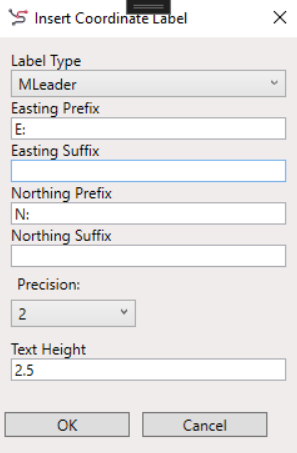
This tool captures the insertion point selected by the user and places a coordinate label showing:
- Easting (X) and Northing (Y) values
- User-defined prefixes and suffixes
- User-specified text height and precision
The tool supports formatting for engineering or mapping standards, making it suitable for:
- Grid intersections
- Control points
- Benchmark locations
- Road centerlines or plot corners

Workflow
- Launch the tool using the COORDLABEL_SP command or from the Labels split menu from the Cartography ribbon tab.
- Fill in your preferred label options in the dialog.
- Click OK and pick a point in your drawing.
- The coordinate label is inserted at the selected location using the chosen format and settings.
Output Examples
- MLeader: E: 521240.70 N: 3940518.19
- MText
- Block: Annotated block with attributes EASTING and NORTHING, editable via properties palette.

Notes
- All values are derived from the current UCS (User Coordinate System).
- Use consistent prefixes/suffixes to adhere to project labeling standards.
- Ideal for use in plans, cross-sections, grid layouts, and map books.