Overview
In standard CAD environments, the OFFSET command is widely used to create parallel copies of 2D entities like lines, arcs, and polylines. However, AutoCAD and other CAD software do not natively support offsetting 3D polylines, making it challenging for users working in 3D space to generate parallel features. This limitation poses a major hurdle in civil engineering, topographic modeling, and 3D design workflows where parallel alignments or elevation-based contours are needed.
The Offset 3D Polyline tool in SPCAD bridges this gap. It allows users to create a spatially offset version of an existing 3D Polyline, preserving the elevation (Z-values) and geometry while offsetting the curve laterally in the XY plane.
This tool is essential in scenarios such as:
- Firstly, creating parallel road or canal alignments from a baseline
- Secondly, designing shoulder lines, ditches, or drainage lines alongside surveyed centerlines
- Additionally, generating contours or construction boundaries offset from original 3D geometry
- Lastly, modeling levees, berms, or offset utility paths in 3D terrain
Workflow Steps
- Launch the Tool
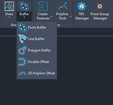
Start the 3D Polyline Offset command from the SPCAD Ribbon (Analysis Panel) or type the command OFFPL3_SP.
- Select the Source 3D Polyline
Click on the 3D Polyline you want to offset.
- Enter the Offset Distance
Type in a positive or negative value.- Positive values offset to the right (based on polyline direction)
- Negative values offset to the left
- Result
A new 3D Polyline is created parallel in plan (XY) but with Z-values restored from the original 3D Polyline.
Tips
- Works on open and closed 3D polylines.
- For curves, the tool segments based on polyline approximation (treats arc segments as linear).
- Be cautious with complex geometries; sharp corners or overlapping geometries may affect offset accuracy.
- The tool places the resulting polyline on the current layer for visibility control.